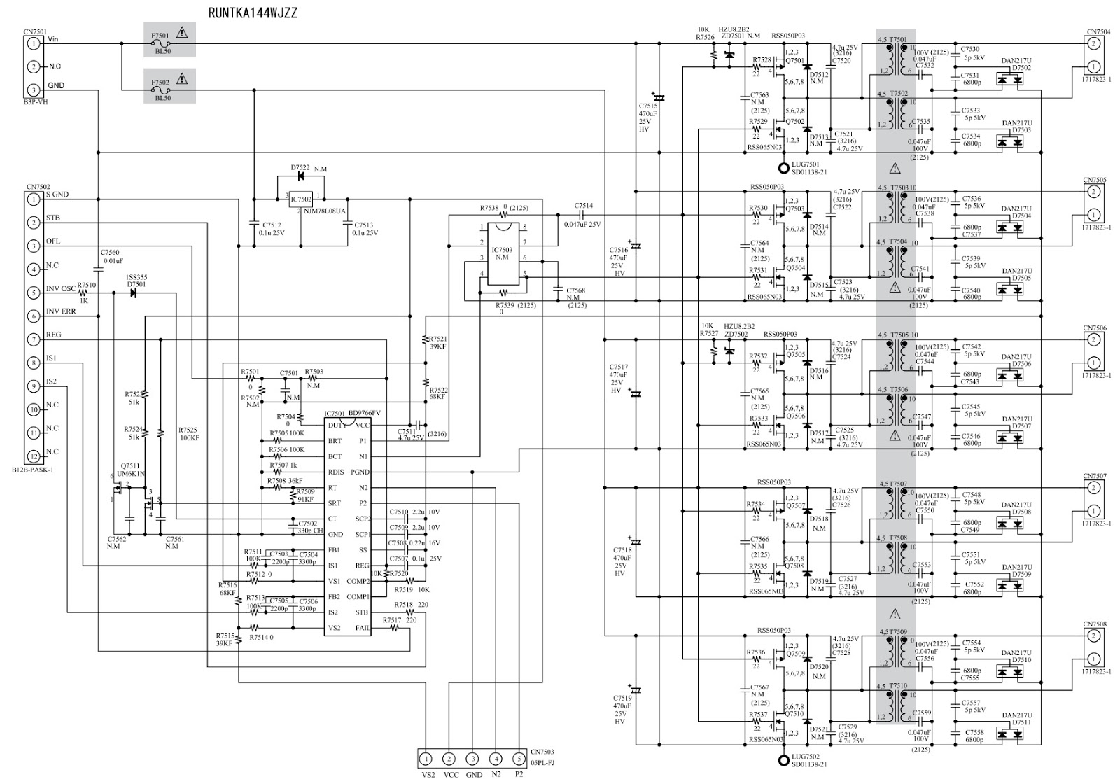
Sharp Inverter Circuit Diagram
Inverter diagram circuit adjustments mode 2and pwb Electrohelponline: sharp lc32gd7e how to enter service mode 5kva ferrite core inverter circuit
The topology of high-frequency inverter with parasitic elements
Frequency parasitic topology Inverter circuit diagram using sg3524 and mosfet Diagram block inverter watt inverters 200watt operation circuits control electronic eleccircuit output projects transistors two figure
Inverter electro
Inverter schematic circuit adjustments pwbElectro help: lc20sh1-e Inverter circuit diagram pwm 5kva core ferrite sinewave homemade sine circuits board solar transformer working calculation details choose system waveInverter mosfet 555 ne555 timer eleccircuit sine sg3524 volts 50hz transformer frequency amplifier figure1.
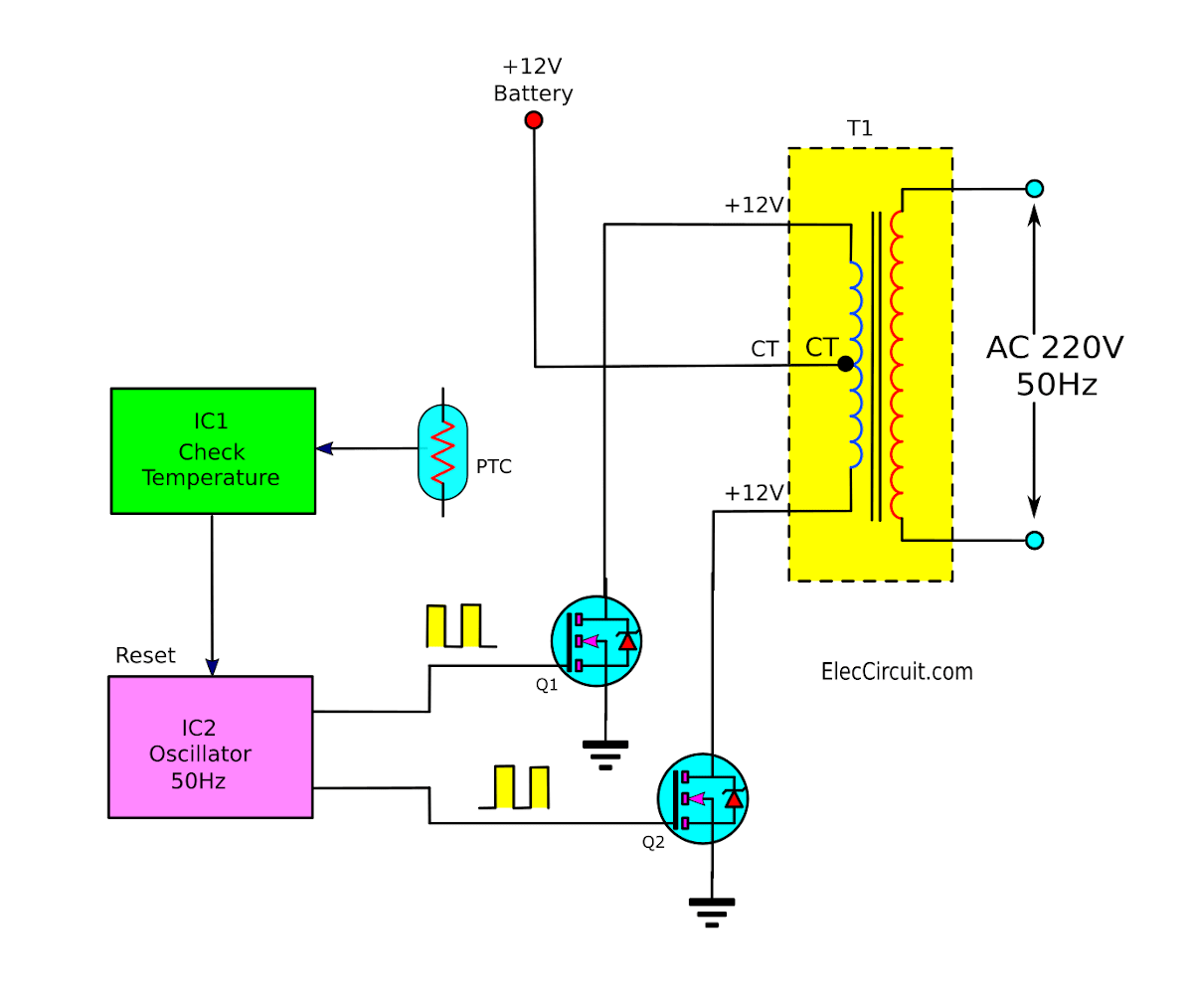
Operation of 200 watt inverter diagramThe topology of high-frequency inverter with parasitic elements Electrohelponline: sharp lc32gd7e how to enter service mode.


5kva Ferrite Core Inverter Circuit - Full Working Diagram with

Electro help: LC20SH1-E - SHARP - SCHEMATIC DIAGRAM [Circuit Diagram

Electrohelponline: Sharp LC32GD7E How to enter service mode

Electrohelponline: Sharp LC32GD7E How to enter service mode

The topology of high-frequency inverter with parasitic elements

Operation of 200 watt inverter diagram | ElecCircuit.com